Raspberry Pi 3 i2c Display wird nicht erkannt

Moin moin,

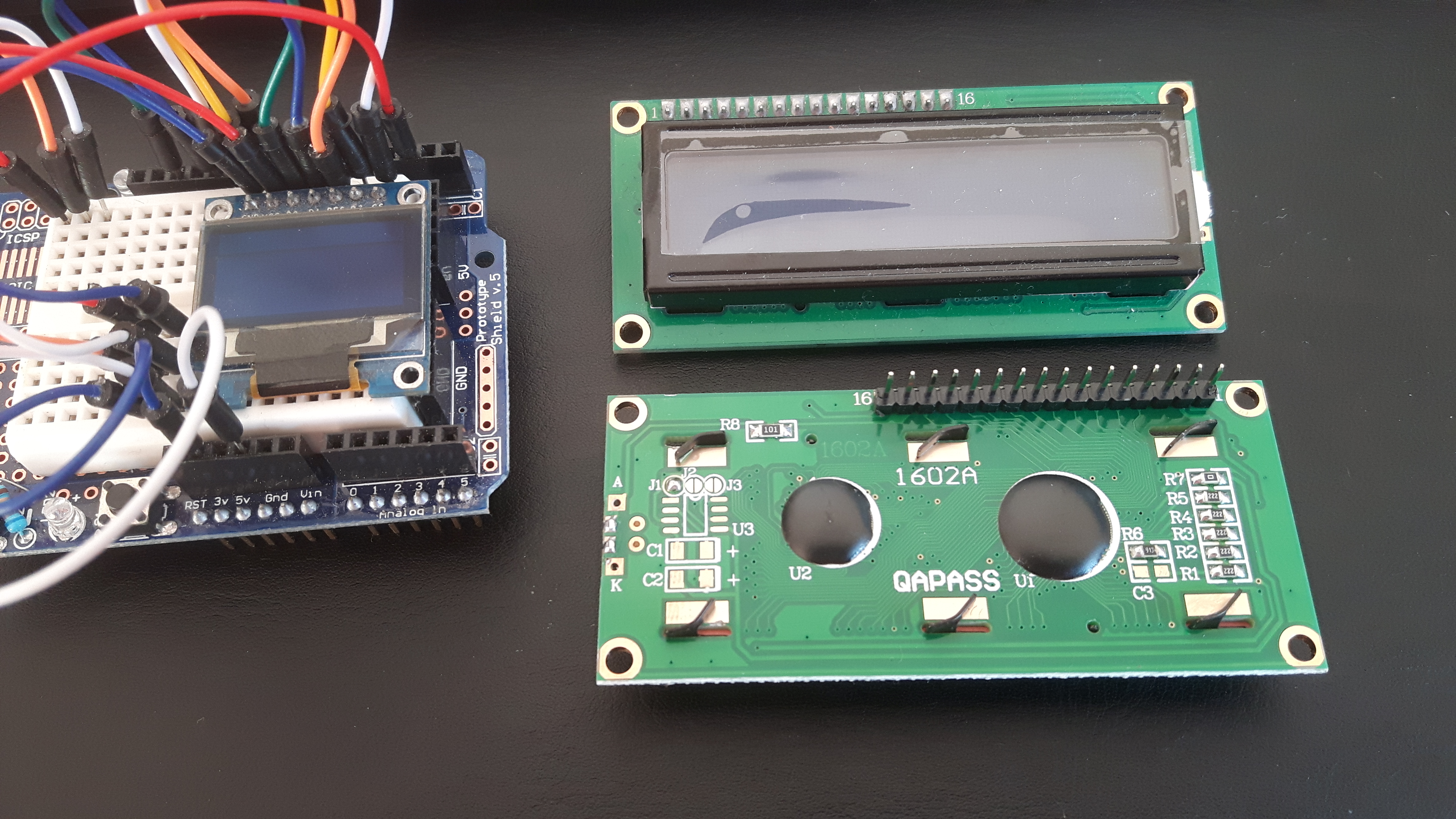
ich versuche gerade ein LCD Display an meinem Raspberry Pi 3 zum laufen zu bekommen. Habe schon viel probiert, aber nichts funktioniert. An das Display habe ich einen i2c Controller angelötet um GPIO Ports zu sparen. Leider wird das Display nicht erkannt.

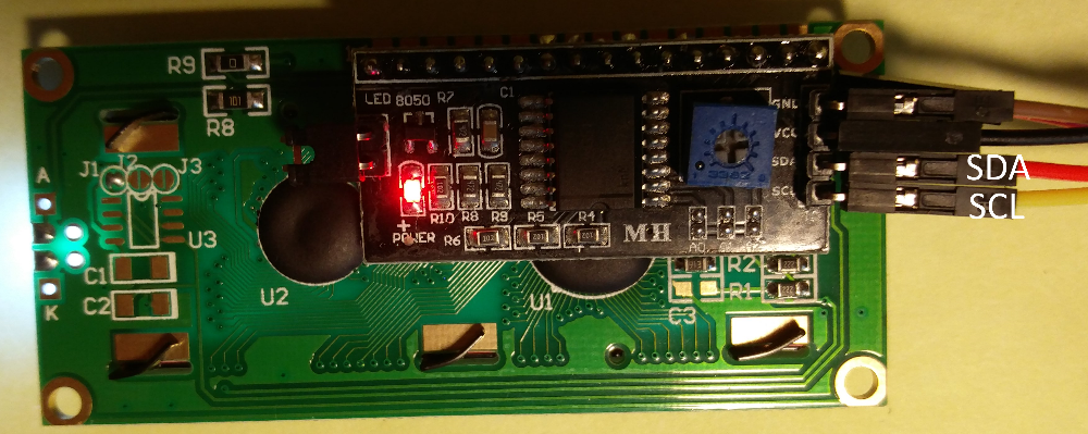
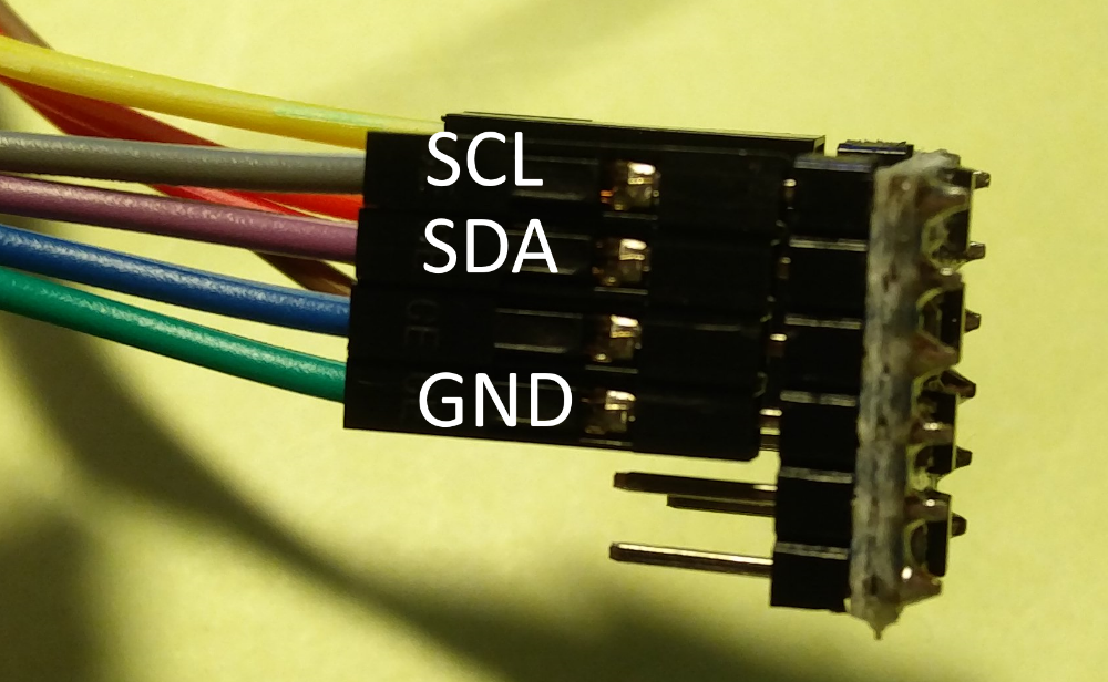
Hier ein Bild vom Controller:

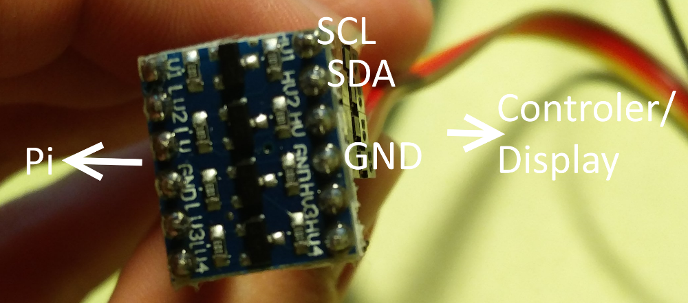
Das ganze geht dann an einen Pegelwandler um die 5V vom Display auf 3,3V für die GPIO Ports zu wandeln:

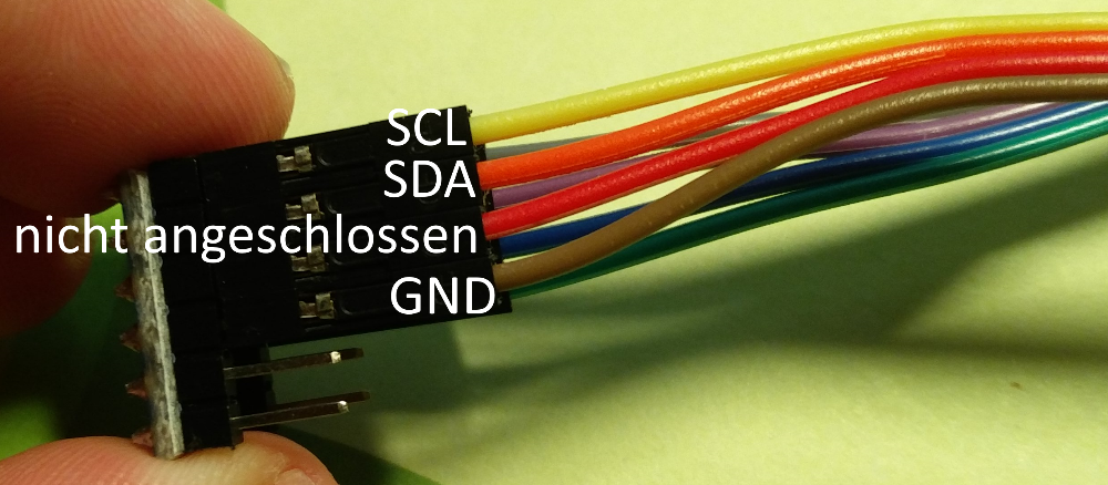
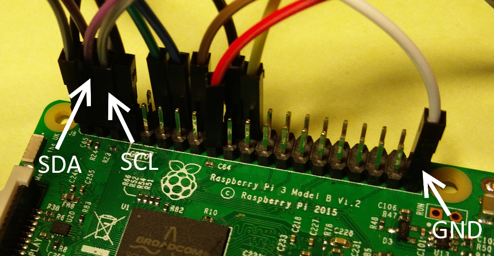
Ich habe die Kabel an die i2c Pins angeschlossen (Pin Belegung habe ich von hier)

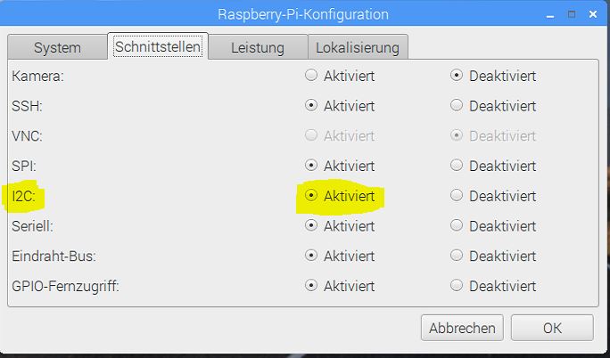
in der raspi config ist die i2c Schnittstelle aktiviert:
raspi%20config

Das ist die /etc/modules

# /etc/modules: kernel modules to load at boot time.
#
# This file contains the names of kernel modules that should be loaded
# at boot time, one per line. Lines beginning with "#" are ignored.

i2c-dev
w1_gpio
w1_therm
i2c-bcm2708

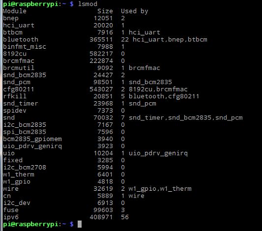
Die /etc/modprobe.d/raspi-blacklist.conf ist leer, die i2c-tools sind installiert, lsmod findet die instalierten ic2 Module:
lsmod

Das ist die /boot/config.txt:

# For more options and information see
# http://rpf.io/configtxt
# Some settings may impact device functionality. See link above for details

# uncomment if you get no picture on HDMI for a default "safe" mode
#hdmi_safe=1

# uncomment this if your display has a black border of unused pixels visible
# and your display can output without overscan
#disable_overscan=1

# uncomment the following to adjust overscan. Use positive numbers if console
# goes off screen, and negative if there is too much border
#overscan_left=16
#overscan_right=16
#overscan_top=16
#overscan_bottom=16

# uncomment to force a console size. By default it will be display's size minus
# overscan.
#framebuffer_width=1280
#framebuffer_height=720

# uncomment if hdmi display is not detected and composite is being output
#hdmi_force_hotplug=1

# uncomment to force a specific HDMI mode (this will force VGA)
#hdmi_group=1
#hdmi_mode=1

# uncomment to force a HDMI mode rather than DVI. This can make audio work in
# DMT (computer monitor) modes
#hdmi_drive=2

# uncomment to increase signal to HDMI, if you have interference, blanking, or
# no display
#config_hdmi_boost=4

# uncomment for composite PAL
#sdtv_mode=2

#uncomment to overclock the arm. 700 MHz is the default.
#arm_freq=800

# Uncomment some or all of these to enable the optional hardware interfaces
dtparam=i2c_arm=on
#dtparam=i2s=on
dtparam=spi=on
dtparam=i2c1=on

# Uncomment this to enable the lirc-rpi module
#dtoverlay=lirc-rpi

# Additional overlays and parameters are documented /boot/overlays/README

# Enable audio (loads snd_bcm2835)
dtparam=audio=on

dtoverlay=w1-gpio
dtoverlay=i2c-rtc,pcf8574
enable_uart=1

Wenn ich jetzt sudo i2cdetect -y 1 ausführe bekomme ich folgendes Ergebnis:
i2c

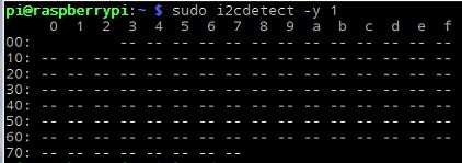
Hat jemand einen Hinweis für mich was ich falsch mache?

Danke!

1 „Gefällt mir“

Und das Display ist auch auf i2c eingestellt? Meist haben die doch Widerstände die man an die entsprechende Position löten muss.

Das kann ich mir nicht vorstellen. Da war nichts weiter dabei, und die einzigen freien Lötstellen auf dem Diaplay sind oben auf dem ersten Bild zu sehen. ich habe nichts was ich da drauf löten könnte.

Das habe ich auf ebay gekauft, der Verkäufer hat gesagt das das auch mit einem Raspberry funktioniert:

In einigen Anleitung werden die Datenleitungen direkt ohne den Pegelwandler an den Pi angeschlossen. Das traue ich mich nicht, ich hatte irgendwo gelesen das die 5V führen und die GPIO Ports das nicht vertragen.
Beispiel dafür diesen youtube Video:

Achso ein LCD1602 (rechts), dachte du meinst einen OLED (links), die können mehrere Übertragungsstandards von Haus aus wenn man die Widerstände entsprechend verlötet.


Aber du hast ja einen I2C Controller auf der Rückseite verlötet, dann macht das Sinn.
Kann ich leider nicht mit weiterhelfen, Raspberries falen nicht in meine Expertise, aber unser @eagleeye wink wink kennt sich vielleicht damit aus.

also die IC2 Sachen kann man direkt anlöten da muss nix dazwischen

siehst du irgendwas am LCD Display?

Aber warum wandelst du die 5 auf 3V um das liefert der PI doch alles
hast du dein Display auch mal ohne Controller getestet?

Ohne den Pegelwandler wird das Display gefunden, es bekommt die Adresse 27. So weit, so gut.

Das nächste Problem taucht bei der Programmierung auf:

import java.io.IOException;

import com.pi4j.component.lcd.impl.GpioLcdDisplay;
import com.pi4j.gpio.extension.pcf.PCF8574GpioProvider;
import com.pi4j.gpio.extension.pcf.PCF8574Pin;
import com.pi4j.io.gpio.GpioController;
import com.pi4j.io.gpio.GpioFactory;
import com.pi4j.io.gpio.GpioPinDigitalOutput;
import com.pi4j.io.gpio.PinState;
import com.pi4j.io.i2c.I2CBus;
import com.pi4j.io.i2c.I2CFactory.UnsupportedBusNumberException;


public class Display2
{
	public static void main(String args[]) throws UnsupportedBusNumberException, IOException
	{
	    System.out.println("Start");
		
	    final GpioController gpio = GpioFactory.getInstance();
	    final PCF8574GpioProvider gpioProvider = new PCF8574GpioProvider(I2CBus.BUS_1, PCF8574GpioProvider.PCF8574_0x27);

	    GpioPinDigitalOutput rsPin = gpio.provisionDigitalOutputPin(gpioProvider, PCF8574Pin.GPIO_00,PinState.LOW);
	    GpioPinDigitalOutput strobe = gpio.provisionDigitalOutputPin(gpioProvider, PCF8574Pin.GPIO_02,PinState.LOW);
	    GpioPinDigitalOutput d4 = gpio.provisionDigitalOutputPin(gpioProvider, PCF8574Pin.GPIO_04,PinState.LOW);
	    GpioPinDigitalOutput d5 = gpio.provisionDigitalOutputPin(gpioProvider, PCF8574Pin.GPIO_05,PinState.LOW);
	    GpioPinDigitalOutput d6 = gpio.provisionDigitalOutputPin(gpioProvider, PCF8574Pin.GPIO_06,PinState.LOW);
	    GpioPinDigitalOutput d7 = gpio.provisionDigitalOutputPin(gpioProvider, PCF8574Pin.GPIO_07,PinState.LOW);
	
	    GpioLcdDisplay lcd = new GpioLcdDisplay(2, 16, rsPin.getPin(), strobe.getPin(), d4.getPin(), d5.getPin(), d6.getPin(), d7.getPin());
	           
	    lcd.clear();
	    lcd.setCursorHome();
	   
	    lcd.writeln(1,"Hello!*");
	    
	    try 
	    {
			Thread.sleep(10000);
	    } 
	    catch (InterruptedException e) 
	    {
			e.printStackTrace();
	    }
	    
	    System.out.println("Ende");
	}
}

Sobald ich diese Zeile final PCF8574GpioProvider gpioProvider = new PCF8574GpioProvider(I2CBus.BUS_1, PCF8574GpioProvider.PCF8574_0x27)aufrufe, geht das Display aus.

Also habe ich etwas anderes probiert:

import com.pi4j.component.lcd.impl.I2CLcdDisplay;
import com.pi4j.io.i2c.I2CBus;

public class Display 
{

	/**
	 * @param args
	 * @throws Exception
	 */
	public static void main(String[] args) throws Exception {
		System.out.println("Start");
		I2CLcdDisplay lcd = new I2CLcdDisplay(2, 16, I2CBus.BUS_1, 0x27, 3, 0,
				1, 2, 7, 6, 5, 4);
		lcd.clear();
		lcd.setCursorHome();
		lcd.writeln(0, "Hello!*");
		lcd.writeln(1, "Hello!*");
		try 
		{
			Thread.sleep(10000);
		} 
		catch (InterruptedException e) 
		{
			e.printStackTrace();
		}
		System.out.println("Ende");
	}

} 

Hier bleibt das Display zwar an, zeigt aber auch keinen Text.

hat jemand eine Idee was ich falsch mache?

hmmm zu viele komische Zahlenwerte :wink:
mein Tipp ist dass du mit den Werten mal rumspielst und kontrollierst